The following describes the process and setup of how I made my Lightwave RF device controller, from an arduino, a few components, and a Raspberry Pi.
This post will grow out with more information as I add it, but this in the position now where it’s ready to be put out there.
Downloads
This release contains two parts
- Arudino Sketch and libraries needed to compile this
- PHP Web Application
To get this working, you might want to read through the rest of this which details the Arduino circuit to put together, and the setup of the php application itself.
The PHP web application needs MySQL, and should create the database on startup, though you’ll need to ensure after unzipping that the ‘config.php’ has necessary write permissions for the web user (chmod 777 the config.php file if you’re lazy like me 🙂 )
You can download the source here:
https://github.com/dpembo/lightwave-control
Components/Tools Required:
Assembly
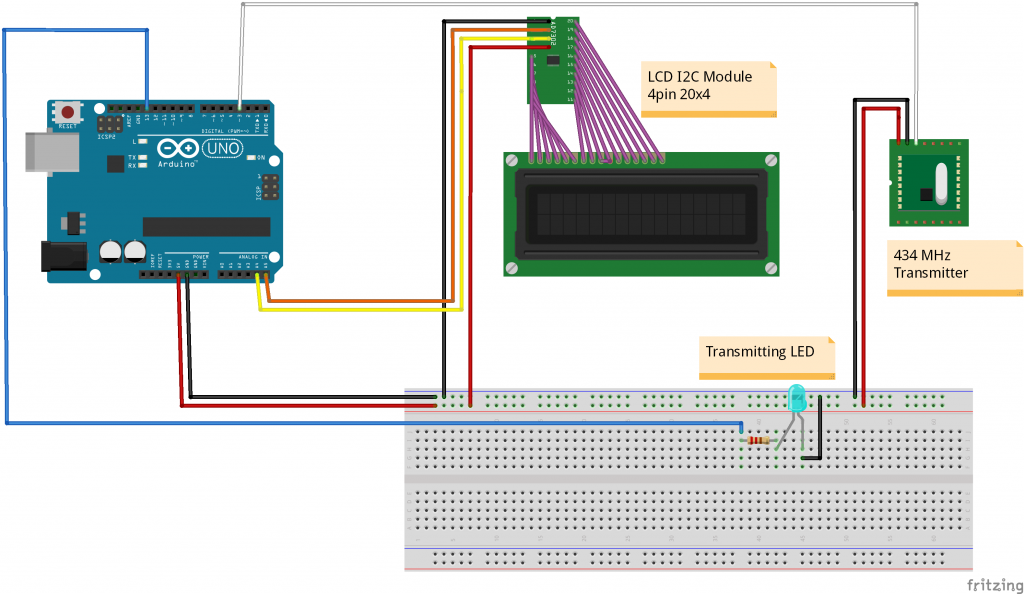
The following diagram shows a simplified assembly. Note the LCD Serial module is one whole module, just shown as two separate components on the diagram. The transmitter is a 433.92Mhz (called 433 or 434MHz transmitters from various places)
Assembly Instructions
- 433.92MHz transmitter – attach the data pin to digital pin 3. Supply a +5V and ground from the breadboard
- LCD I2C Serial Module – has a 4 pin connection. 2 for data, and the +5V and ground. Although this is shown in the diagram as 2 components, they can be purchased as a single module. The module can be wired either with a set of jumper cables (female to male), or via a 4 pin cable and some header pins into the breadboard, and then cables from there to the Arduino. Data connections are wired into analogue pins 4 and 5
- Transmitted LED. Wire in ground, and Pin 13 as the power
- Soldered a 17.3cm coiled wire to the transmitter to extend the range
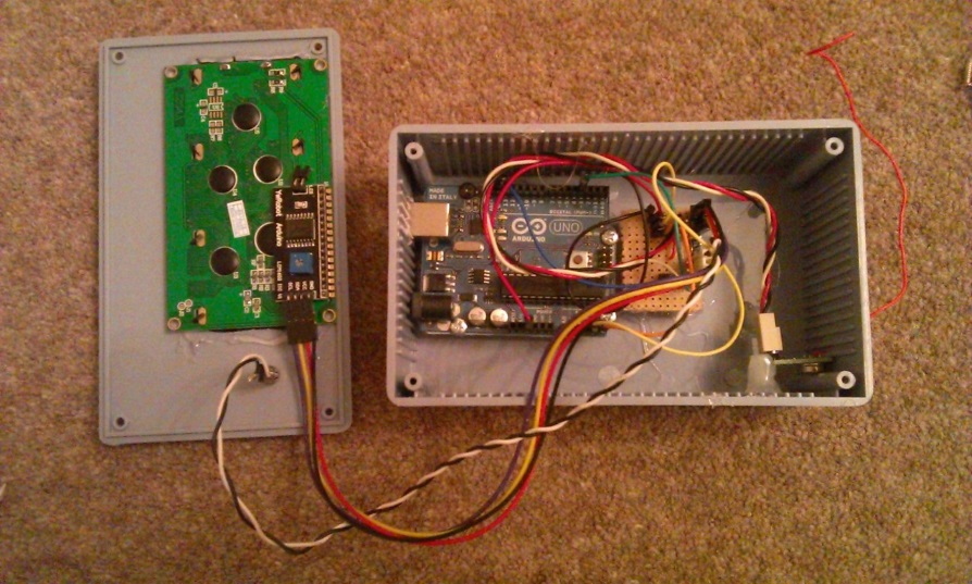
Wired into a breadboard (in a messy way unlike the diagram above) here’s what my prototype looked like:
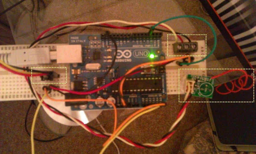
3 areas of interest are highlighted in the photo
- Left – 4 pin cable, connected into the breadboard via header pins (which fell out pretty easily!). This goes to the LCD I2C Serial display
- Right top – 3 pin connector to the transmitter module. Here I used a screw terminal connector, as my cable was recycled from an old computer PSU so there was only a 3 pin connector on one end.
- Right middle – the transmitter, connect by a 3 pin cable, note the coiled cable for the antenna. The recommended length appeared to be 17.3cm
Note – the transmitting LED was not connected here. For prototype, I just relied on the one inbuilt into the Arduino on pin 13
Prototype was tested using the serial monitor within the Arduino IDE by placing a lightwave RF device in pairing mode, and supplied the following command over serial:
#111235190237183123100Lounge*
The format of the message is as follows
| Description |
Length |
Values |
Example |
Notes |
| Start |
1 |
# |
# |
Start with a # |
| Transmitted ID |
18 |
[0-9](18) |
111235190237183123 |
Has to be 18 chars |
| On/Off |
1 |
[0/1] |
1 |
1=on 0=off |
| Dim Level |
2 |
[00-31] |
31 |
31 = Max
01 = Min00 = Ignore |
| Description |
15 |
[aA-zZ] |
Lounge |
Up to 15 characters – if more will wrap around |
| End |
1 |
* |
* |
End with a * |
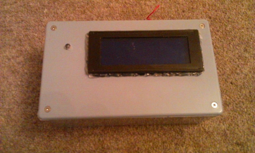
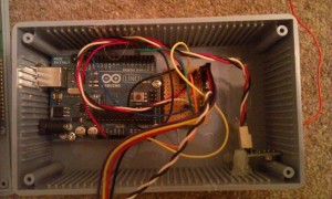
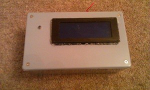
Finished Product
Assembly instructions
- Wired and soldered all components into the strip board, simplified over the breadboard layout slightly
- Using the multi-tool, cut opening in the lid suitable for the LCD screen
- Drill small hole in the lid big enough to push through the LED
- Drill hold in right hand side for antenna cable
- Mount Arduino onto hexagonal spacers using screens.
- Align Arduino inside project box, mark and cut hole using rotary multi-tool for the USB cable.
- Use glue gun to glue Arduino/spacers to the project box
- Use glue to stick LCD display (and LED if needed) into place on the lid
- Use glue gun or sealant to seal the display lid and fill and gaps
- Glue spacers on strip board, glue to project box base.
- Glue spacers in project box to hold the transmitter in place
Photos

Raspberry PI Setup
Installation
- Install Apache/PHP and MySQL on the raspberry pi
- Unzip the developed web application into the webserver.
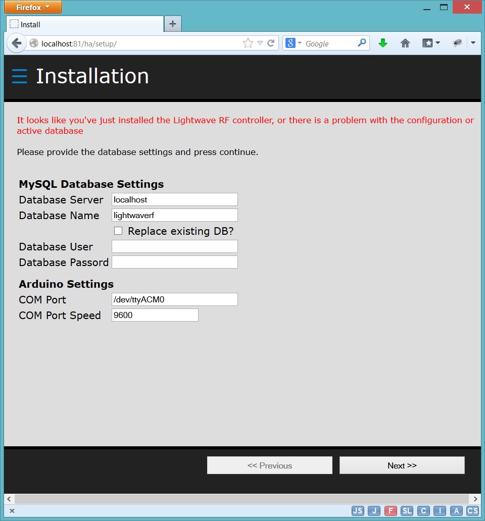
- Using a browser on the network, connect into the URL where you unzipped the device to. This should open the setup/installation screen.

- Configure the COM Port to that of the Arduino, and provide the database settings needed, then press the ‘Next >>’ button to install. If there are any errors, observe the message and correct as needed (e.g. permissions on the config.php file)
Device Setup
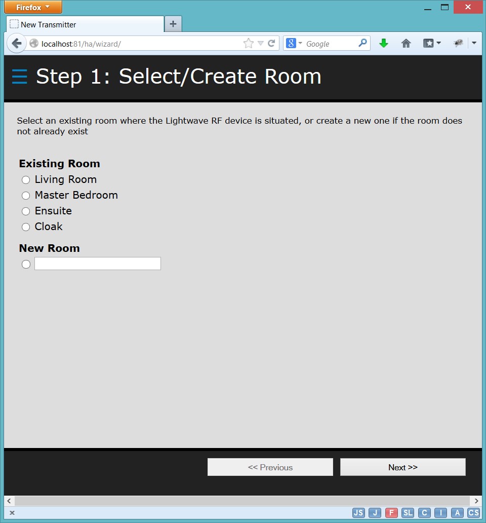
Once installation has been completed successfully, you’ll be taken to the setup wizard to add any Lightwave devices you may have:
Step through the wizard to
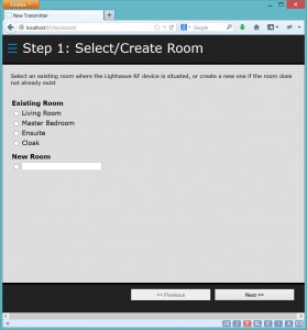
a) Select or create a room – devices are grouped by room in the user interface
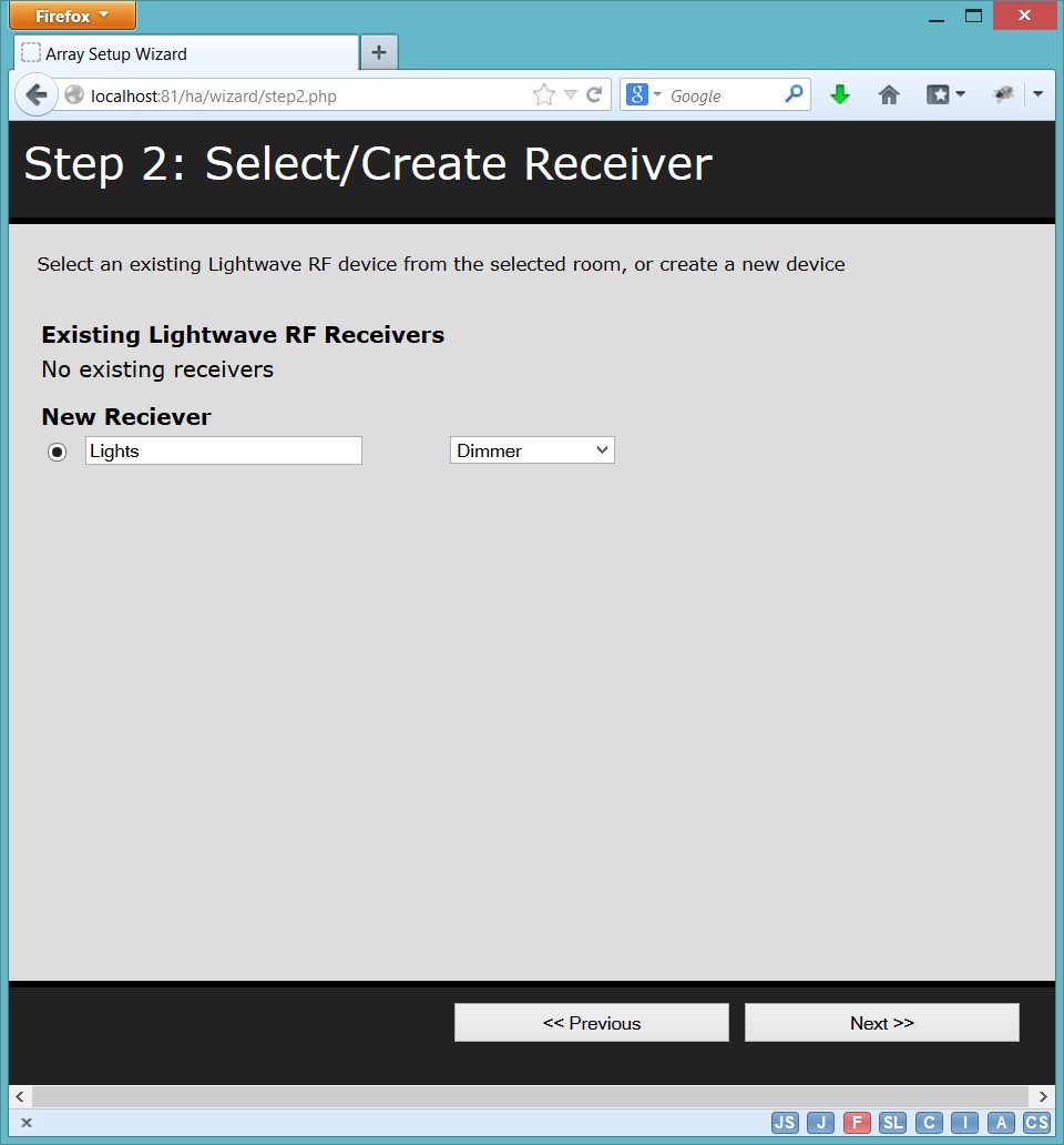
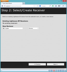
b) Add the receiver (The actual lightwave RF device). Here you add give it a description and select the type of receiver, e.g. dimmer, socket, relay, etc.
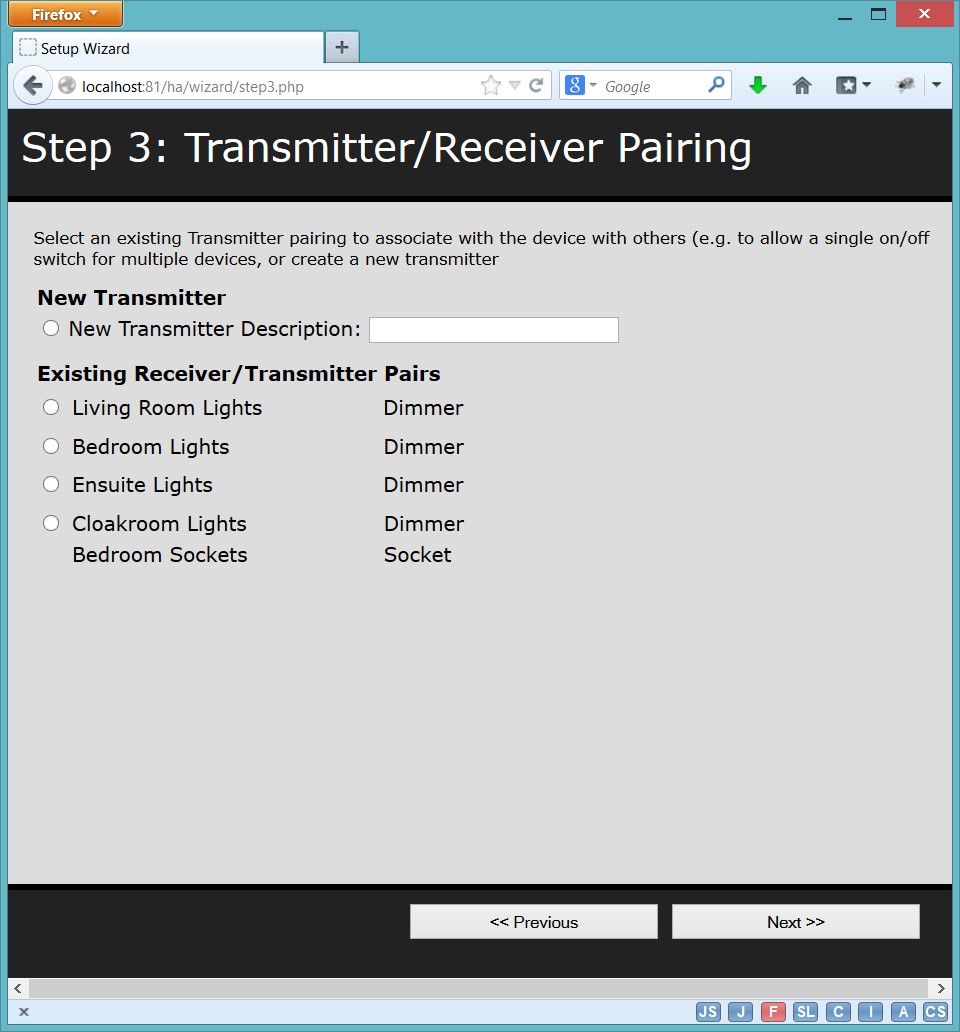
c) Following addition of the receiver is to create a transmitter identifier. This uniquely allows the transmitter to be associated with a single receiver, or multiple receivers. For example, you can reuse the same transmitter for a room to turn on more than one device from the same command. You’ll notice in the following screenshot that the final transmitter covers 2 receivers. If you want the control to be unique, just pick new transmitter and enter a description.

d) That’s enough configuration and your room, receiver and transmitter are all recorded and linked. The final stage is to actually pair the transmitter and receiver together. To do this, you need to put your receiver into pairing mode (e.g for a dimmer, hold both buttons. For a socket hold the single button. For relay, push in and hold the pairing button with a pen).
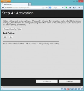
Once the device shows it’s in pairing mode (usually by flashing the lights) you need to transmit a code for the transmitter. The wizard allows you to do this, and then once the receiver confirms a pairing, you can test this with the off/on buttons.
Once paired, finally press the finish button.
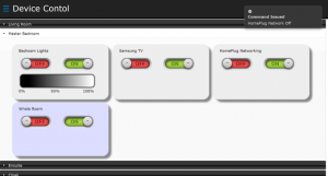
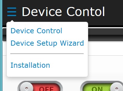
Device Control
You’ll then be presented with the device control screen where you can control your Lightwave RF devices

From here you can select the room, and chose to power on/off the devices, and where the device is a dimmer, you can choose to adjust the dim by clicking or touching the dim ‘gradient’ bar.
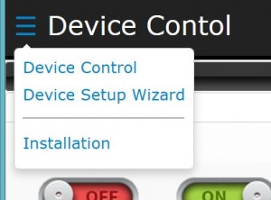
If you want to change the setup or reinstall, you can use the menu in the top left corner.
On transmission, it should looks like this!
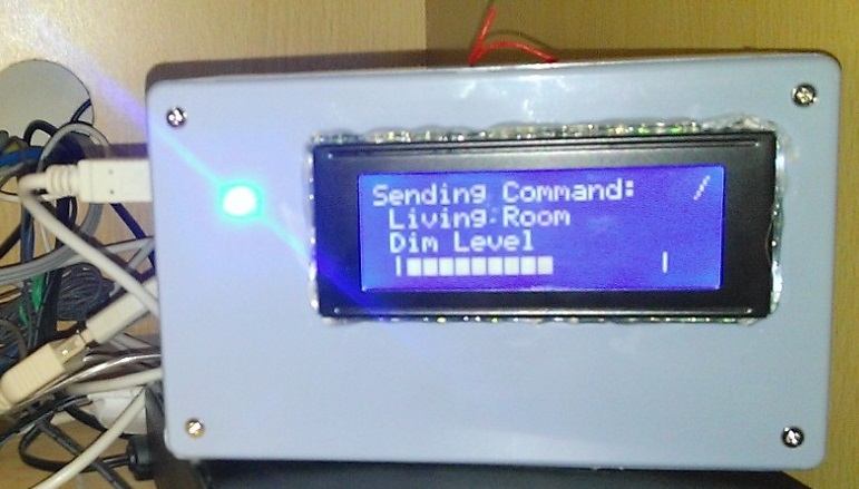
Like this – buy me a beer?