
The following describes the process and setup of how I made my Lightwave RF device controller, from an arduino, a few components, and a Raspberry Pi.
This post will grow out with more information as I add it, but this in the position now where it’s ready to be put out there.
Downloads
This release contains two parts
- Arudino Sketch and libraries needed to compile this
- PHP Web Application
To get this working, you might want to read through the rest of this which details the Arduino circuit to put together, and the setup of the php application itself.
The PHP web application needs MySQL, and should create the database on startup, though you’ll need to ensure after unzipping that the ‘config.php’ has necessary write permissions for the web user (chmod 777 the config.php file if you’re lazy like me 🙂 )
You can download the source here:
https://github.com/dpembo/lightwave-control
Components/Tools Required:
- Arduino (Uno or equivalent)
- 433MHz Transmitter Module
http://hobbycomponents.com/index.php/433mhz-wireless-modules-mx-fs-03v-mx-05.html - 20×4 LCD I2C Module
http://hobbycomponents.com/index.php/i2c-2004-serial-20-x-4-lcd-module.html - LED & Appropriate Resistor
- Wires
- Breadboard
- Matrix/Vero board
http://www.maplin.co.uk/p/2939-srbp-matrix-board-strip-jp47b - Hexagonal spacers (risers)
http://www.maplin.co.uk/search?text=Maplin+Hexagonal+Threaded+Spacer+20mm+10+Pack - Single row header pins
http://hobbycomponents.com/index.php/0-1-2-54mm-40way-sil-turned-pin-m-f-headers-pack-of-5.html - 1 x 4 pin cable (LCD 12C)
http://hobbycomponents.com/index.php/cables/4-way-pin-anti-reverse-cable-30cm.html - 2 x 3 pin cable (transmitter and led)
http://hobbycomponents.com/index.php/cables/3-way-jumper-cable-20cm.html - Project Box
http://www.maplin.co.uk/p/hammond-general-purpose-abs-plastic-boxbgy-grey-112x62x31mm-n74bq - Raspberry PI
- Necessary USB Cables
- Power Tools:
- Soldering Iron
- Rotary Multi-tool
- Glue gun
Assembly
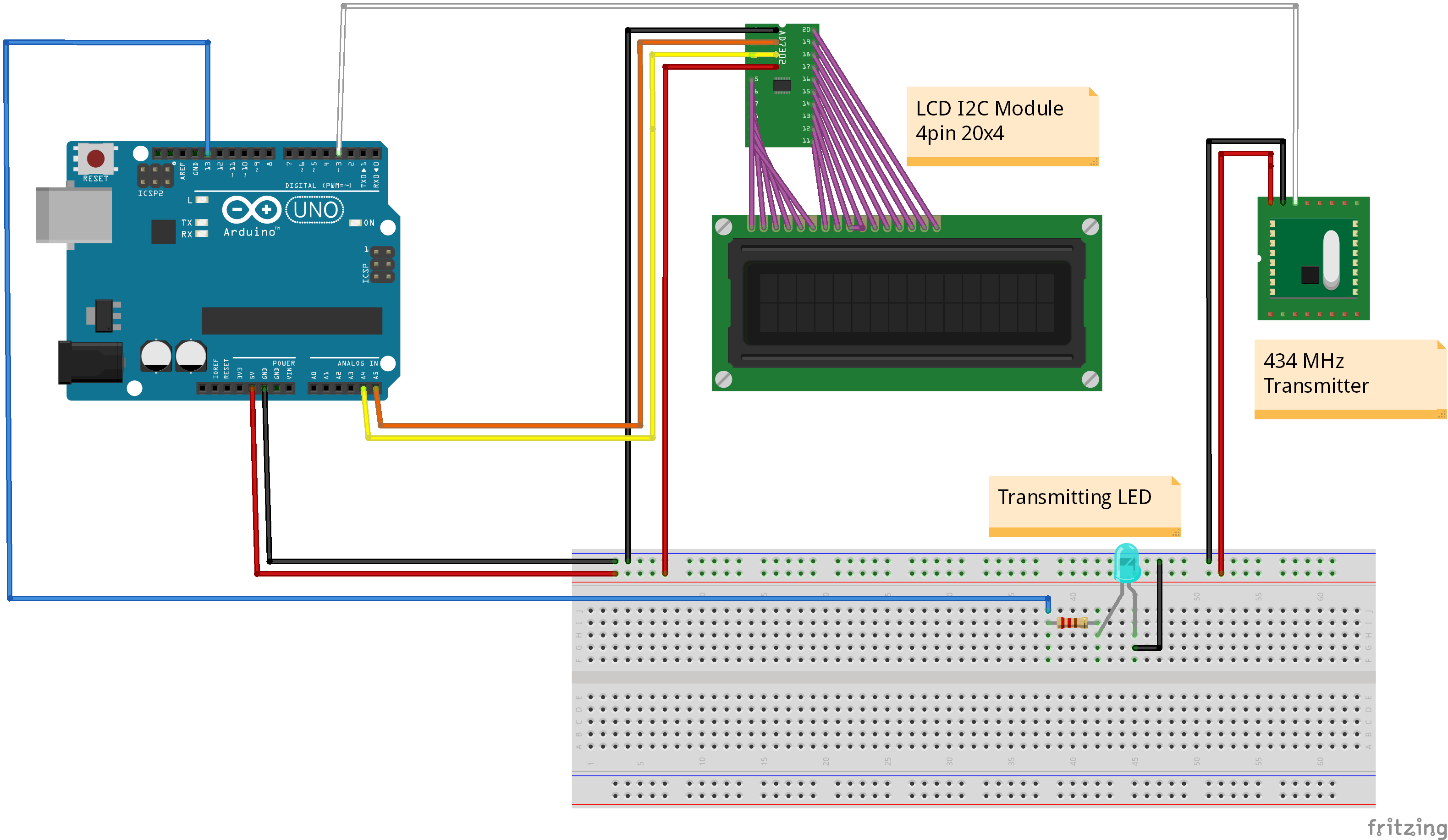
The following diagram shows a simplified assembly. Note the LCD Serial module is one whole module, just shown as two separate components on the diagram. The transmitter is a 433.92Mhz (called 433 or 434MHz transmitters from various places)
Assembly Instructions
- 433.92MHz transmitter – attach the data pin to digital pin 3. Supply a +5V and ground from the breadboard
- LCD I2C Serial Module – has a 4 pin connection. 2 for data, and the +5V and ground. Although this is shown in the diagram as 2 components, they can be purchased as a single module. The module can be wired either with a set of jumper cables (female to male), or via a 4 pin cable and some header pins into the breadboard, and then cables from there to the Arduino. Data connections are wired into analogue pins 4 and 5
- Transmitted LED. Wire in ground, and Pin 13 as the power
- Soldered a 17.3cm coiled wire to the transmitter to extend the range
Wired into a breadboard (in a messy way unlike the diagram above) here’s what my prototype looked like:
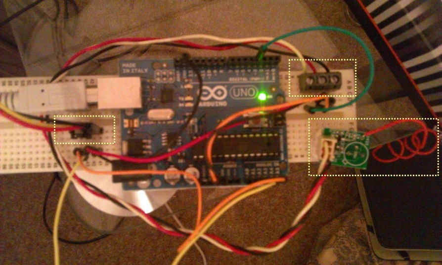
3 areas of interest are highlighted in the photo
- Left – 4 pin cable, connected into the breadboard via header pins (which fell out pretty easily!). This goes to the LCD I2C Serial display
- Right top – 3 pin connector to the transmitter module. Here I used a screw terminal connector, as my cable was recycled from an old computer PSU so there was only a 3 pin connector on one end.
- Right middle – the transmitter, connect by a 3 pin cable, note the coiled cable for the antenna. The recommended length appeared to be 17.3cm
Note – the transmitting LED was not connected here. For prototype, I just relied on the one inbuilt into the Arduino on pin 13
Prototype was tested using the serial monitor within the Arduino IDE by placing a lightwave RF device in pairing mode, and supplied the following command over serial:
#111235190237183123100Lounge*
The format of the message is as follows
| Description | Length | Values | Example | Notes |
|---|---|---|---|---|
| Start | 1 | # | # | Start with a # |
| Transmitted ID | 18 | [0-9](18) | 111235190237183123 | Has to be 18 chars |
| On/Off | 1 | [0/1] | 1 | 1=on 0=off |
| Dim Level | 2 | [00-31] | 31 | 31 = Max 01 = Min00 = Ignore |
| Description | 15 | [aA-zZ] | Lounge | Up to 15 characters – if more will wrap around |
| End | 1 | * | * | End with a * |
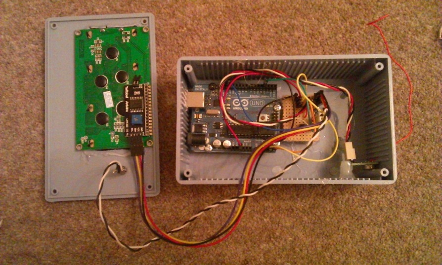
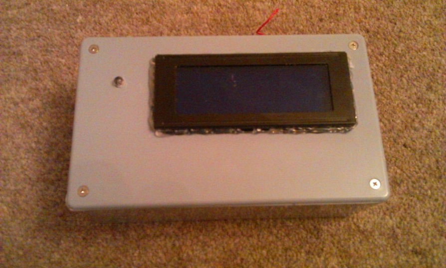
Finished Product
Assembly instructions
- Wired and soldered all components into the strip board, simplified over the breadboard layout slightly
- Using the multi-tool, cut opening in the lid suitable for the LCD screen
- Drill small hole in the lid big enough to push through the LED
- Drill hold in right hand side for antenna cable
- Mount Arduino onto hexagonal spacers using screens.
- Align Arduino inside project box, mark and cut hole using rotary multi-tool for the USB cable.
- Use glue gun to glue Arduino/spacers to the project box
- Use glue to stick LCD display (and LED if needed) into place on the lid
- Use glue gun or sealant to seal the display lid and fill and gaps
- Glue spacers on strip board, glue to project box base.
- Glue spacers in project box to hold the transmitter in place
Photos

Raspberry PI Setup
Installation
- Install Apache/PHP and MySQL on the raspberry pi
- Unzip the developed web application into the webserver.
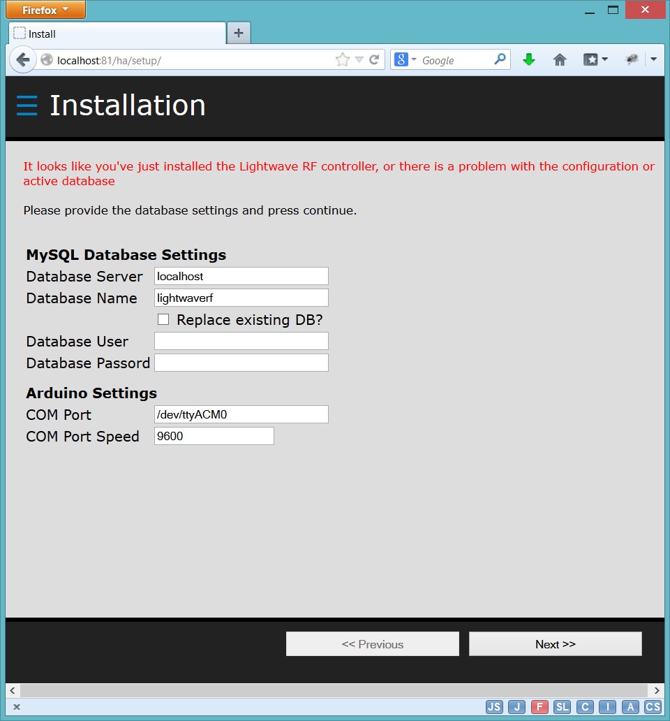
- Using a browser on the network, connect into the URL where you unzipped the device to. This should open the setup/installation screen.

- Configure the COM Port to that of the Arduino, and provide the database settings needed, then press the ‘Next >>’ button to install. If there are any errors, observe the message and correct as needed (e.g. permissions on the config.php file)
Device Setup
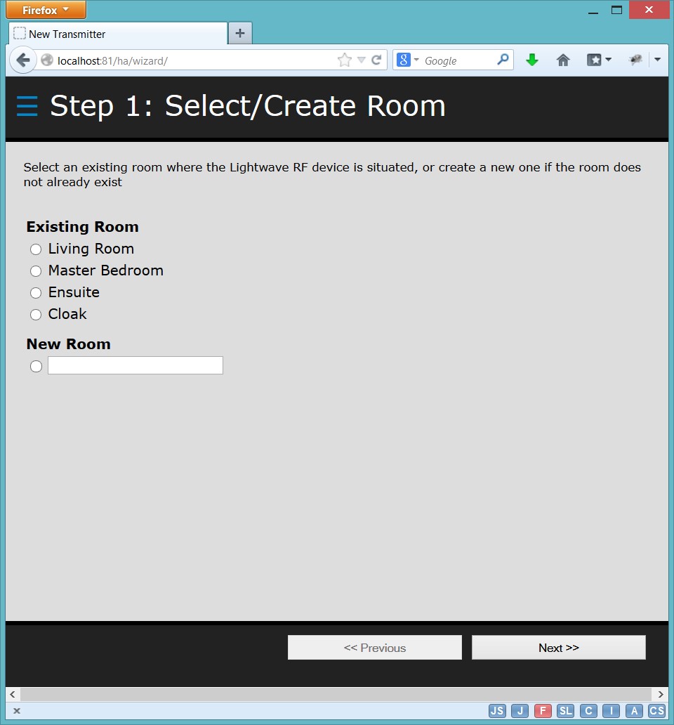
Once installation has been completed successfully, you’ll be taken to the setup wizard to add any Lightwave devices you may have:
Step through the wizard to
a) Select or create a room – devices are grouped by room in the user interface
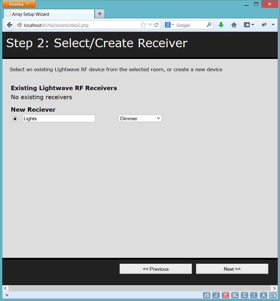
b) Add the receiver (The actual lightwave RF device). Here you add give it a description and select the type of receiver, e.g. dimmer, socket, relay, etc.
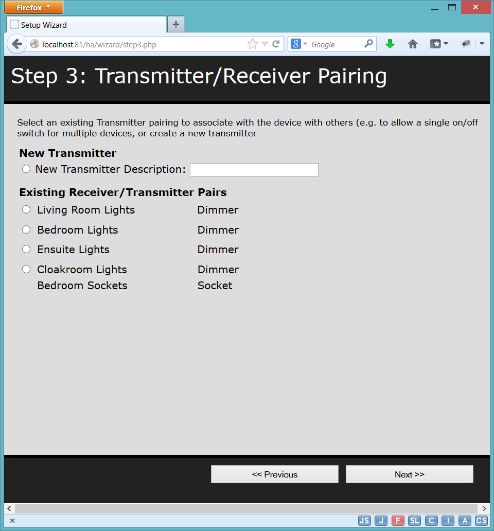
c) Following addition of the receiver is to create a transmitter identifier. This uniquely allows the transmitter to be associated with a single receiver, or multiple receivers. For example, you can reuse the same transmitter for a room to turn on more than one device from the same command. You’ll notice in the following screenshot that the final transmitter covers 2 receivers. If you want the control to be unique, just pick new transmitter and enter a description.
d) That’s enough configuration and your room, receiver and transmitter are all recorded and linked. The final stage is to actually pair the transmitter and receiver together. To do this, you need to put your receiver into pairing mode (e.g for a dimmer, hold both buttons. For a socket hold the single button. For relay, push in and hold the pairing button with a pen).
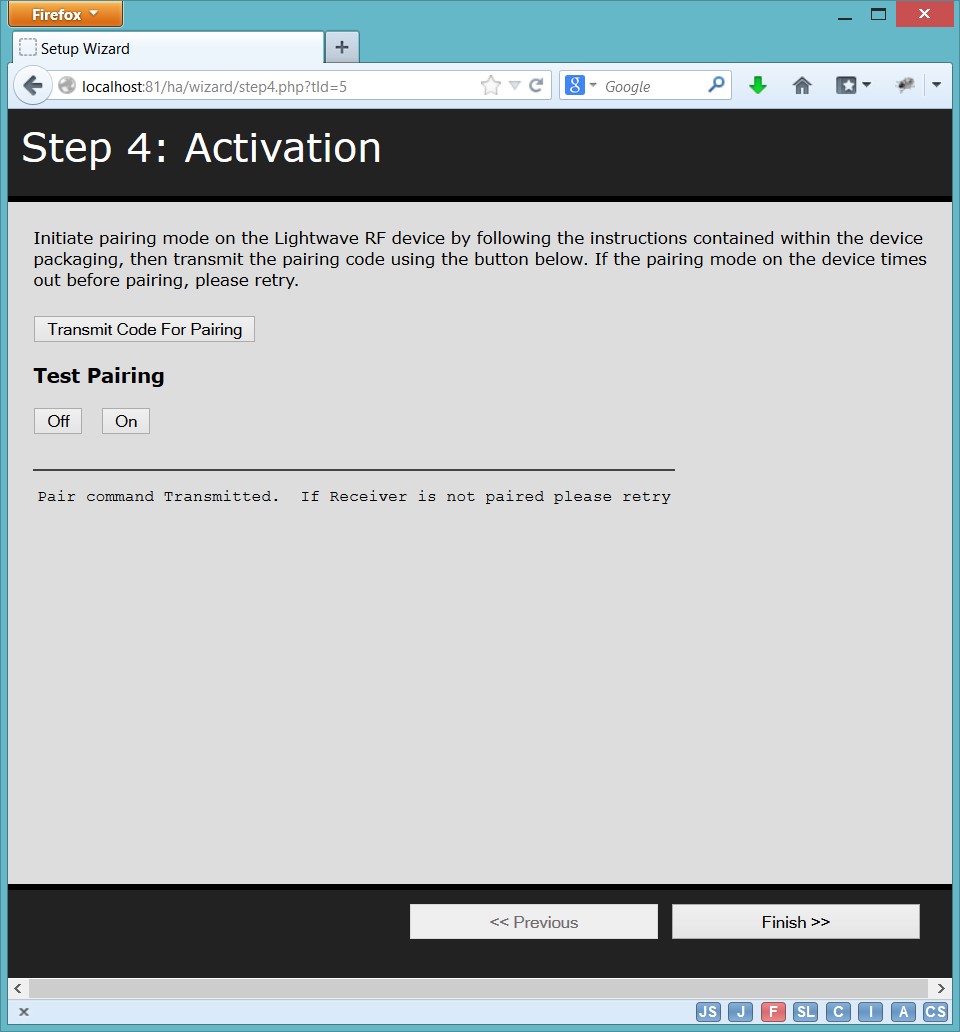
Once the device shows it’s in pairing mode (usually by flashing the lights) you need to transmit a code for the transmitter. The wizard allows you to do this, and then once the receiver confirms a pairing, you can test this with the off/on buttons.
Once paired, finally press the finish button.
Device Control
You’ll then be presented with the device control screen where you can control your Lightwave RF devices
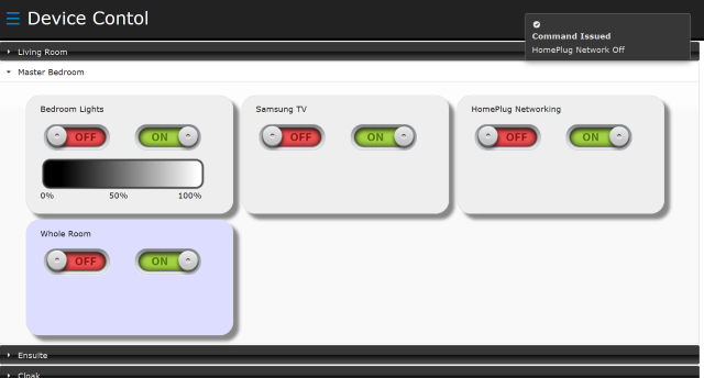
From here you can select the room, and chose to power on/off the devices, and where the device is a dimmer, you can choose to adjust the dim by clicking or touching the dim ‘gradient’ bar.
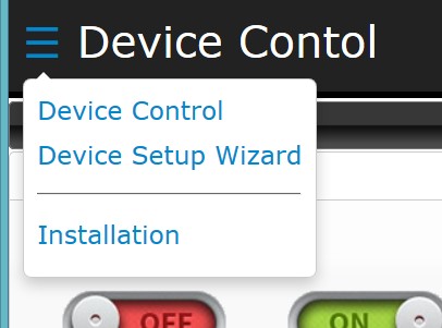
If you want to change the setup or reinstall, you can use the menu in the top left corner.
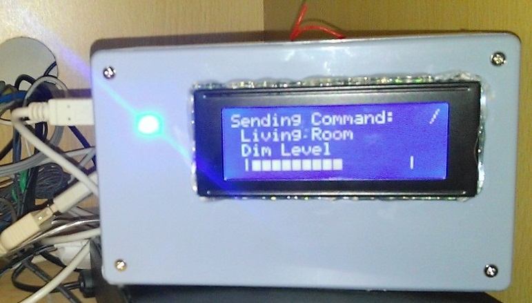
On transmission, it should looks like this!
Hi this is a great write up and exactly the sort of thing i’ve been looking for as i’m just starting kitting out my house with LightwaveRF devices. However, I was wondering about the use of the Arduino…. Couldn’t the wireless module just be hooked up to the GPIO of the RasPi rather than requiring an additional micro controller?
Any sign of that source code you mentioned at the top?
Cheers,
Luke
Luke, thanks for taking the time to comment.
I’ve been improving the code over the last few weeks.
I’ve added in a schedule function that can activate any device at a chosen date/time, interval or even at sunset, I still need to post this here.
I’ve already created the google code project, but haven’t had the time to upload the code yet. As you’re interested, I’ll upload this at the weekend!
In terms of using the RPIs GPIO ports, I did contemplate this but was concerned over the timing, and as there was already working examples of the arduino and LightwaveRF devices working together, I decided to go this way, but I’m still contemplating trying this on a second RPI at some point!
Definitely a great write-up and has been very useful as I start thinking about doing something similar.
In my case, I want to control electric heaters and a dehumidifier based on readings from a temperature and humidity sensor.
Is this functionality that would make sense within your software. If so, I would be very happy to develop and contribute it.
Thank you for putting this together.
Hi Pembo,I\’d love to try out your code. It is exactly what I am looking for! I already have an rf transmitter and receiver hooked up to me Arduino. Please upload soon :)Simon
All, I’ve just uploaded the code. You’ll find the release here http://www.pembo.co.uk/2014/04/28/lightwave-rf-control-v0-9-beta-1-release/
I’m in the process of uploading to google code as well… if there are any issues/questions, just add a comment to the release post for now, but I’ll try and get the google code page setup with an issue tracker/etc.
Please remember it’s early 🙂
Many of the pages miss validation/etc, so won’t force you to enter something that’s mandatory!
Anyone who has downloaded the source and/or tried to follow this, I’d appreaciate any feedback on the beta.
Thank you very much for sharing your project. You might want to look at using a Spark Core. – Sort of Arduino compatible.https://www.spark.io/Also some one is trying to port the code.https://community.spark.io/t/lightwaverf-library-port-for-spark/4179/40I am just trying to construct an IR Blaster to control to control all my AV devices TV, cable box etc. Once I have finished that. I will have a look to see if I can control my LightwaveRF devices with the same Spark.Really small / cheap and I hope can be operated by battery.Best wishes.
This looks fantastic! Thanks for making this available. It looks like a lot of hard work has gone into this.
I have ordered an Arduino Uno and the transmitter just for this project. I’m hoping to use it with my media center setup. Dim the lights when a movie/tv show starts etc.
I’ll pop in an update when it’s done if you’re interested?
Thanks again
I’d love to see someone take this forward further.
I’ve been making a few more changes to the code that I’ll upload at some point soon.
Please be aware that Megaman have changed the dimmers now – theres a JSJS400 model rather than a JSJS200 model of dimmers, and for some reason this doesn’t respond to the off signal.
I need to do some more investigation into this, which could well involve picking up a 400MHz receiver and listening to the ‘broadcasts’ to work out what is different from the official message over that which the API generates. I’ve been intouch with Megaman and they are investigating, but as they still work with the lightwave RF transmitters, it’s not an issue they are going to push lots of resource onto.
Hello. Just what I was looking for. Very nice project, wery well written. I’am actullay just at the middle of the installation. Arduino bit done, just updating/upgrading the Pi. I’am not to sure about something in step 4.
“Configure the COM Port to that of the Arduino, and provide the database settings needed, then press the ‘Next >>’ button to install. If there are any errors, observe the message and correct as needed (e.g. permissions on the config.php file)”
Configure COM port? I assuming the Arduino has to be plugged in to the Pi’s USB port, is this correct?
Thank You
Hello. Managed to setup everything, permission, etc.. Unfortunatelly, it dont seems to be working with JSJSLW320WH wall socket..Just won\’t pair with it. Should this be working, or additional setup required?Thank You
Hi – It should work with the wall sockets. The only issues I’ve found are with the new dimmers which I’m still looking into.
I’ve updated the download with the latest and greatest.
Grab the download again and see if this resolves your issue. You’ll probably need to delete the MySQL DB, or create a new one as I think there were some changes here.
Assuming you’ve got the COM port right, it should transmit the message.
You can also try the transmission yourself through the arduino ide serial panel, grabbing most of the data from the HTML page for the test. If you can’t figure out a test message, let me know and I’ll post an example that you can push into the arduino direct.
Thank You for your reply. Unfortunately I did not managed to get this working..:-( Everything seems fine, when I transmit the pairing code, the display indicates the sending sequence, but wont pair.
I tested my transmitter with another arduino project, and it is working. I have the trasmitter data pin connected to (digital) pin3..Is this correct?
Also tried the transmission through arduino serail panel, but had no luck..:-(
On the transmitter, the part number as follows: B63962
Thank you
Must be something to do with the transmitter I guess – you should be able to test the command over serial and pair this up with a device! Sorry.
There’s a hidden debug in the serial comms. Send through an @ character and it’ll put the serial comms in debug mode so if you’re testing via the serial console, you can see at least what is going through…
This is excellent! Just what I\’ve been looking for.This will be a project for the next few months in between changing nappies.Thanks for putting in all the work.
have you any thoughts on how to use the RF receiver that comes with the transmitter to take cues from lightwaverf remotes and sensors?
Did you give permission over the serial port?Mine was on /dev/ttyUSB0 and I had to edit permission so that the web service could open it.
@Pembo,
Very Nice work!
I’ve set this up to day. I don’t have a compatible LCD so I’m a bit blind on the Arduino side ATM but it seems to be working ok.
How long after a button press does it take for the socket to switch on your setup?
Mine takes over 5 seconds to react.
I think this is mostly php run time, so I wanted to compare it to yours.
Is this just that the raspberry pi is a terrible web-server?
(Also, I think there is a bit of a bug in the code, there appears to be non-relative paths in your code, in order to get this to work I had to put the entire site code inside a /var/www/ha sub-dir.)
Do you plan to implement moods?
I’d like to have macro buttons so I can press one button and set every lightwave socket/bult/switch to specific levels. This would let us expand on the very limited mood switches you can get.
Thanks
Tony.
@Pembo,I have been looking at the PHP and this section seems to account for 3 of the 5 seconds of execution time on an event change:line 27 of ha.php==================>$startTime=time();$timeout=3;while(1==1){ $read = $serial->readPort(); if(time() > $startTime + $timeout) { break; }}<===============I can see that the Pi doesn\\'t communicate properly with the Arduino if this three seconds of serial read isn\\'t there, but I can\\'t work out why.Why did you need to add this in?Trying to shorted this down from 3 seconds seems to make the code very unreliable, but I can\\'t quite understand exactly what it\\'s doing as the variable $read doesn\\'t seem to get used anywhere.Thanks for any help you can offer here.T.
Hi – it’s because the arduino reboots on a serial connection to try and make life simple for uploading sketches. You can disable this a couple of ways and this would bring right down the time it takes!
Hi,Just putting this all together at the moment.It seems lightwaveRF.h is missing from the libraries in the project home on Google Code – I was wondering, do you have it knocking about anywhere, or is it one you\\’ve got from somewhere else?(forgive me if I\\’m talking rubbish – I have precisely 30 minutes experience of using an Arduino!)
Thanks Adam, didn’t realise I’d missed this – I’ve now uploaded this into the svn in google code – you’ll find it in the libraries directory.
Thank you – very much appreciated. I’ll download when I get home from work.
As a complete novice for Arduino sketches and Python etc (but quite accomplished at PHP) I’m going to use the 433MHz receiver unit that came with the transmitter as the basis of a learning exercise, and will see if I can hook it up to the Pi directly and incorporate LightwaveRF remotes into the setup.
Hi there,
Like in one of the comments, I was wondering if it’s possible to skip the audrino part and just use the RPi.
I have a pi with transmitter/receveir setup for use with pilight.
Would be great if I could use this setup to control a radiator valve!
Thanks,
Don
It would take a rewrite of the Lightwave library from the arduino code into something the pi could use.
It’s possible, but would take a bit of time and brain power to achieve.
Wish I had the knowledge! I’m just a beginner:)
Hopefully someone will pick this up!:)
HiDid you manage to work out why the JSJS400 don\’t work? Thanks for the great write up.
Yes indeed – someone kindly discovered the issue in the lightwaveRF libaray.
Hi pembo,Can you explain where to change the parameter from to 64 to make the off function work? (sorry if this is a basic question, i\’m new to this and struggling to understand what i\’m doing, although i\’ve managed to get most things working….)
Hi Pembo,Only just seen this post and have the issue with the 400 series dimmers. where in the code does this change need to be made?
Hi,
Has anyone had any luck in creating new ID codes – for some reason, only about 20% of the codes I try actually work – I suspect there’s some sort of checksum.
For example, the example above works, 111235190237183123, and also the following:
111235190237183123
111235190237187123
111235190237189123
But, for example111235190237188123 doesn’t…
Can anyone help me?
Thank you!
Oliver.